
Fig.1 Schematic of one transistor radio
One Transistor Superheterodyne Radio |
It was during early 2018 I've started working on a very unique project -a superheterodyne receiver constructed with just one transistor.
Crazy,huh? Well, it wasn't actually. I was actually following Charlez Wenzel's unique one transistor reflex receivers for a long
period, but couldn't make one still. Those receivers were amazing and were even able to drive a loudspeaker into very comfortable
volumes and when properly constructed, they could even receive distant medium wave stations without any external antenna support.
It was a long overdue project, and once in a while I return back to these receivers with overwhelming curiosity. The curiosity
built overtime finally landed on a very crazy thought. Can I make a superheterodyne radio with just only one transistor that can
power a loudspeaker? Really crazy stuff, indeed!
I became success after a year, and during mid 2019 I created a very unique radio and here it is. It is very straight forward however,
I have never heard of anyone already came up with such a receiver anytime before though, the results in fact encouraged me to open up this webpage :-)
Fig.1 Schematic of one transistor radio
A very special and unique characteristic of this superhet is that the local oscillator function always self modulated by detector audio! It was
then early anticipated that the beat components from mixer function has a potential to distort the final audio output and was quite
correct. The receiver exhibits a slight distortion while peak tuning point is achieved and was effectively eliminated by slightly
off-tuning. While receiving a strong local station, the mixing is powerful, IF gain becomes high and so is the detector output. The
oscilaltions are now modulated and could be even helpful in the further reflex audio voltage build-up.
Version 1(presented here) of this receiver is powerful enough to drive a 4 ohm loudspeaker into roomfilling volume for strong local
medium wave AM modulated signals. It sounds like your regular radio off course. It require only a 9V pp3 battery. The lack of AGC
kick make it less operational on distant/weak signals. My very first prototype used an antenna coil made of 28SWG enamelled wire. I
later did few more experiments to raise the audio level and also weak signal reception intended, using high quality litz wound coil.
Alghough it did help improve the operation, the weak signal reception was still not upto the mark. That said, I did manage to receive
many regular medium to distant stations like a regular radio in whispering mode, fantastic! The lack of AGC means it really lacks
it. You can't make AGC from almost nothing! I did receive bangalore AM 612khz during evening which is almost 500kms away. It's a
stand-alone receiver, not connected to any external antenna support.
There are lot of functions happening in the little BC549C transistor while operation. One such is proximity mode of IF regeneration. This is
a very innovative method of getting IF amplification through regenerating signals via antenna tank circuit. That means the antenna coil is in
proximity with IF transformer -which is unshielded off course- picks some part of the IF and sent back for amplification along with tuned RF.
This is essentially same as Armstrong method of regeneration, but an intermediate frequency is regenerated instead in an already oscillating
device. The effect of IF regeneration is very noticeable in output and it changes as you change the proximity, if no improvement
observed the secondary of the IFT must be reversed. The IFT connections are made for positive feedback and are helpful for regenerative mode of operation.
The one transistor receiver basically amplifies received RF, oscillates, mixes with tuned RF, generates IF products, filters IF,
amplifies the selected IF using proximity mode of regeneration, demodulates and finally amplifies audio. This is the best example for
radio frequency multi-tasking, because a single active device handles lot of functions alltogether.
The BC549C is indeed a high gain device, but you could also use an MPSA18. I have tested both of them without noticing too much difference
in operation. The converter stage amazingly worked well down to 1.5V. The range of oscillations was counted between 1MHz through 2MHz which
is in line with selected IF frequency(455KHz here) and operational bandwidth. Rail supply voltage changes did not affect the oscillations
considerably and I did get steady oscillation bandwidth till the supply voltage decreased down to 1.5V. But the lower voltage levels did
affect the audio output and at 1.5V, everything goes to whispering more -still works!. Increasing the voltage beyond 9V favors a little improving
the output, but not anythying great, so I settled the voltage exactly at 9V DC.
Now for a few people, basic building blocks of a superheterodyne radio is detailed below. You're supposed to have one or more transistor amplifier implemented per each block and that would constitute a 7 or more transistor superhet in traditional configuration. On a side note, this doesn't mean that the one transistor circuit detailed here is better in all the aspects comparing to other complex configurations requiring more number of transistors. But you might have understood it already, the key concept behind this project is to test whether such a complex configuration implementable using just one active device, and this page proves it. The received audio quality is good and programs are enjoyable sitting near to it. If you happen to have a handful of comparatively stronger AM radio stations around, you're not going to hear any difference comparing to a traditional portable radio, but I must say that at present configuration, this radio really lacks weak signal catch capabilities. The received signal power is what makes this design alive and working great. A crystal radio type external antenna configuration is planned to experiment and will probably detailed in another page or as updates here, sometime in future.
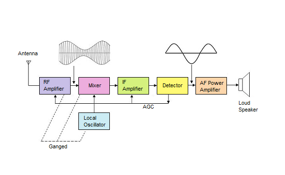
Fig.2 Typical Superheterodyne block diagram
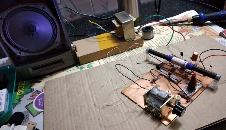
The initial prototype was built on a solderless breadboard. I was really surprised during initial test results and I left it operational for a few weeks. Now an year or more later, I decided to give it a second try using better quality components. The coil was made using litz grade wire an air core variable gang condenser used in place of initial pvc capacitor, the 'Q must have improved and the results too. This is my first manhattan style of construction, it looks relatively easy if you have proper pads in hand. I made those pads by cutting some general purpose tracked pc boards. There are other options too. The shield of IF can must be removed for proper operation of the circuit or else the shield can block regenerative operation detailed above.
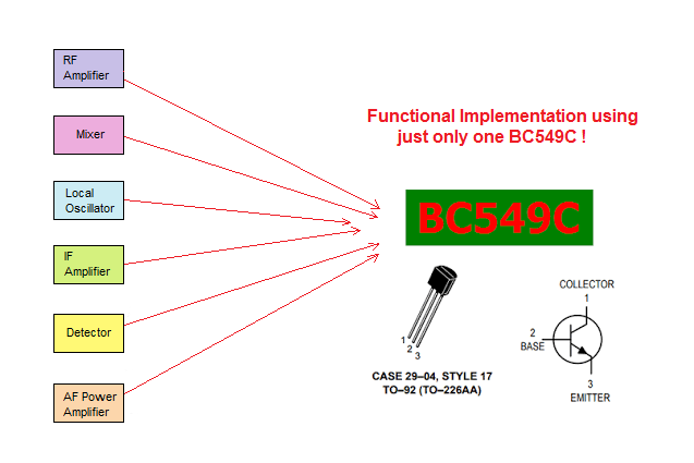
Fig.3 Functional diagram
Layout and how IF regeneration is achieved is represented in the below graphic:
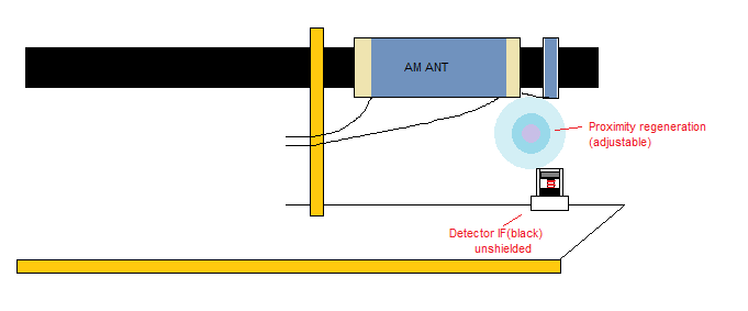
Fig.4 Proximity IF regeneration
|
|
Email: transistor495@gmail.com